Mostrando las entradas con la etiqueta valve. Mostrar todas las entradas

jueves, 4 de octubre de 2018

Safety Relief Valves

The primary function of a safety valve is to protect property and life. Because a safety valve is often the last device to prevent catastrophic failure under pressure conditions, it is important that the valve works at all times i.e. it must be 100% reliable.
Safety valves should be installed wherever the maximum allowable working pressure of a system or pressure containing vessel is likely to be exceeded, in particular under fault conditions due to the failure of another piece of equipment in the system.
Pressure excess can be generated in a number of different ways including:
  • Failure of a cooling system allowing vapour or fluid to expand
  • Compressed air or electrical power failure to control instrumentation
  • Plant fires
  • During the start-up conditions of a plant

The term “Safety Valve” and “Relief Valve” are generic terms to describe a variety of pressure relief devices. A wide range is available based on the application and required performance criteria. The different designs are required to meet numerous national standards.

Definitions
ASME / ANSI PTC 25.3 standards (USA)
Pressure relief valve – (This is a general term, which includes safety valves, relief valves and safety relief valves.)
A spring-loaded pressure relief valve which is designed to open to relieve excess pressure and to reclose and prevent the further flow of fluid after normal conditions have been restored. It is characterised by a rapid-opening 'pop' action or by opening in a manner generally proportional to the increase in pressure over the opening pressure. It may be used for either compressible or incompressible fluids, depending on design, adjustment, or application.
Safety valve - A pressure relief valve actuated by inlet static pressure and characterised by rapid opening or pop action.
Relief valve - A pressure relief device actuated by inlet static pressure having a gradual lift generally proportional to the increase in pressure over opening pressure.
Safety relief valve - A pressure relief valve characterised by rapid opening or pop action, or by opening in proportion to the increase in pressure over the opening pressure, depending on the application, and which may be used either for liquid or compressible fluid.
European standard EN ISO 4126-1

Safety valve - A valve which automatically, without the assistance of any energy other than that of the fluid concerned, discharges a quantity of the fluid so as to prevent a predetermined safe pressure being exceeded, and which is designed to re-close and prevent further flow of fluid after normal pressure conditions of service have been restored.
A Standard Valve

The images below show a standard Relief valve and a standard Safety valve from a well-known UK manufacturer. Each manufacturer does things slightly differently however all of the basic components and principles of operation are the same. As described previously, a safety valve differs from a relief valve in that it opens rapidly once the set pressure has been reached. For the same inlet size and with the valve in the closed position, the surface area that the pressure on the inlet side will see is the same. When the set pressure is reached and the valve starts to open, the disk on a Safety valve is larger (see the diagrams below) and hence the same pressure then sees a much larger surface area and consequently the force increases greatly causing the valve to open quickly and hence the characteristic pop action.

Figure 1 - Lifting lever (3), Spring (4), Spindle (17), Bonnet (6), Inlet body (12), Disk (9), Spring Carrier (16)

The image below shows the above Safety valves and Relief valves dismantled. The disk diameter on the 1" (DN25) Safety valve is only 7mm larger than on the Relief valve which doesnt sound like much, but when you calculate the areas it is an increase of 36%.


A dismantled 1" (DN25) Safety Valve and a dismantled 1" (DN25) Relief Valve from the same Manufacturer
Basic Safety Valve Principles

This diagram represents a Safety valve in its very simplest form. The force acting on the inlet side of the disk is acting against the force applied by the spring plus the force applied by the back pressure on the top of the disk.

Figure 2 - Simple Valve Model

The valve remains closed when(PI x Ab) < Fs + (PB x At), is in equilibrium when(PI x Ab) = Fs + (PB x At) and opens when(PI x Ab) > Fs + (PB x At) were PI = Inlet pressure, PB = Back pressure, At = Top of disk area, Ab = Bottom of disk area. Things to notice from this design are that if PB is variable and quite large relative to PI, then this will cause the pressure at which the valve opens to vary which is undesirable. The following two designs (Fig 3 & Fig 4) are available that eliminate the effect of back pressure on the set pressure.

Figure 3 - Fitted with belows

Figure 4 - Piston design

The bellows prevents backpressure acting on the top side of the disk. In relation to the piston there is no top side within the main body of the valve hence again the back pressure cannot affect the set pressure. Bellows failure is an important concern in critical applications where a very precise set pressure is required. In these cases some mechanism to detect a leak of process medium out of the top vent would be implemented. Piston designs are not usually found in conventional Safety valves but are more common in Pilot Operated Safety valves.

Guidance on when to use Bellows
API 520 Practice Guidelines: a conventional design should not typically be used when the built-up backpressure is greater than 10% of the set pressure at 10% over pressure. European standard EN ISO 4126: the built-up backpressure should be limited to 10% of the set pressure when the valve is discharging at the certified capacity.
Other Backpressure concerns
A large PB will also affect the flowrate of the valve when open.
The total backpressure is generated from two components, superimposed backpressure and the built-up backpressure

Superimposed back pressure: the static pressure that exists on the outlet side of a closed valve.
Built-up back pressure: the additional pressure generated on the outlet side when the valve is discharging.

In a conventional design (no bellows), the superimposed backpressure will affect the opening characteristic and set value, but the combined backpressure will alter the closing (blowdown) and re-seat value.
Performance Summary

Overpressure is the percentage over the set pressure by which the valve is fully open. The blowdown is the percentage below the set pressure by which the valve is fully closed.

Figure 5 – Relationship between pressure and lift for a typical safety valve

Table 1 – Safety Valve Performance Summary

Table 2 – Safety Valve Standards

Components of an API Safety Valve
Please note depending upon the manufacturer they may differ slightly to that shown below.


Figure 6 – Typical Safety Valve Components

The basic elements of the design are right angle pattern valve body, inlet can be either a full nozzle or a semi-nozzle type. With a full nozzle design has the “wetted” inlet tract formed from one piece (as per figure 6) with the seat integrated into the top of the nozzle. The internal bore of the nozzle and the disc is the only part of the valve that is exposed to the process fluid with the valve in the closed position. A semi-nozzle design consists of a seating ring fitted into the body.The disc is held onto the seat by the stem, with the downward force coming from the compression on the spring mounted in the bonnet. The amount of compression on the spring is adjusted by the spring adjuster under the cap.
Bonnet Types

Figure 7 - Open Bonnet


Figure 8 - Closed Bonnet

Typical Cap Options
Open Lifting Lever
A lifting mechanism is recommended to test for correct valve operation at all times where corrosion, caking, or any deposit could prevent the opening operation.
Foreign particles can lodge under the seat of the valve when it discharges. The lifting lever allows you to lift the valve and flush the obstruction. Pressure relief valves for Section VIII require a lift lever on all air, steam, and hot water valves used at temperatures over 60 degC. Typically used where periodic testing of the valve in location is desired to assure its operation. With an Open lifting lever design, when the valve discharges, fluid media will escape into the atmosphere around the open lifting lever assembly. If this is not desirable or when back pressure is present you would select a Packed Lifting Lever design.
Packed Lifting Lever

Figure 10 - Packed Lifting Lever

As described above, this type is selected where leakage of the media to the atmosphere during valve discharge or during back pressure would be un-desirable. A packed lever design is a completely sealed assembly.
Bolted Cap
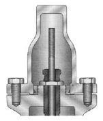

Figure 11 - Bolted Cap

Some people consider a bolted and gasketed design better to the standard screw cap for applications with back pressure and / or vibration hence some manufacturers offer this as an option.
Gag Screw / Test Gag

Figure 12 - Gag Screw / Test Gag

Under certain circumstances i.e. under the start-up conditions of a plant or to pressure test the system in a controlled environment, it may be required that the valve is prevented from opening.This is achieved by screwing the bolt (shown on the wire) into the cap which screws down onto the stem and prevents it lifting. Obviously it is important that test gags are removed prior to placing the valve into service.
Other Typical Options Available
Balanced Bellows


Figure 13 - Balanced Bellows

The bellows is designed to cover the same area on the back of the disc equal to the seat area hence the back pressure will have no effect on the set pressure. See the previous section “Basic Safety Valve Principles”. Bellows also protects the spindle, spindle guide and spring from the process medium.
Operation Indicator

Figure 14 - Operation Indicator

A micro switch is fitted on the exterior of the valve which is activated when the stem rises in the valve.
Steam Jackets

A bolt on steam jacket for preserving the valve body temperature. Typically used on fluids to prevent solidification of the flowing viscous fluids.

Safety Valve Operation
A disc is held against the nozzle by a spring, which is contained in a cast bonnet. The spring is adjusted by a compression screw to permit the calibration of opening or set pressure. An adjustable nozzle ring, threaded onto the nozzle, controls the geometry of the fluid exit control chamber (also known as a huddling chamber). The control chamber (huddling chamber) geometry is very important in controlling valve opening and closing pressures and stability of operation. The nozzle ring is locked into position by a ring pin assembly as shown in Figure 15 below.


Figure 16 - Relationship of Nozzle Area to Control Chamber (Huddling Chamber)

Under normal system operation the valve remains in the closed position because the spring force (Fs) is greater than the system pressure acting on the internal nozzle seating area (PA). If system pressure increases to a point when these forces are equal, then the set pressure is reached. The disc lifts and fluid flows through the valve. When pressure in the system returns to a safe level, the valve closes.
Just prior to reaching set point, the pressure relief valve leaks system fluid into the huddling chamber. The fluid now acts on a larger area of the disc inside the huddling chamber (PAh), causing the valve to experience an instantaneous increase in the opening force. Refer to the figure 16 above to see relationship between Nozzle Area (A) and the Huddling Chamber Area (Ah). System pressure acting on the larger area will suddenly open the safety relief valve at a rapid rate.
Although the opening is rapid and dramatic, the valve does not open fully at set point. The system pressure must increase above set point to open the valve to its full lift and capacity position. Maximum lift and certified flow rates will be achieved within the allowable limits (overpressure) established by various codes and standards. All pressure relief ales are allowed an overpressure allowance to reach full rated flow. The allowable over pressure can vary from 10% to 21% on unfired vessels and systems, depending on the sizing basis, number of valves, and whether a fire condition is encountered.
Once the valve has controlled the pressure excursion, system pressure will start to reduce. Since the huddling chamber area is now controlling the exit fluid flow, system pressure must reduce below the set point before the spring force is able to close the valve. The difference between the set pressure and the closing pressure is called blowdown, and is usually expressed as a percentage of set pressure. The typical blowdown can vary from 7% to 10%, the industry standard.
The nozzle ring adjustment changes the shape and volume of the huddling chamber, and its position will affect both the opening and the closing characteristics of the valve. When the nozzle ring is adjusted to its top position, the huddling chamber is restricted to its maximum. The valve will usually pop very distinctly with a minimum simmer (leakage before opening), but the blowdown will increase. When the nozzle ring is lowered to its lowest position, minimal restriction to the huddling chamber occurs. At this position, simmer increases and the blowdown decreases. The final ring position is somewhere between these two extremes to provide optimal performance.
Liquid Service Operation
On liquid service, a different dynamic situation exists. Liquids do not expand when flowing across orifices, and a small amount of fluid flow across the nozzle will produces a large local pressure drop at the nozzle orifice. This local pressure drop causes the spring to reclose the valve if the fluid flow is minimal. Liquids leaking into the huddling chamber can quickly drain out by gravity and prevent fluid pressure from building up in the secondary area of the huddling chamber. Liquid relief valves are thus susceptible to a phenomenon called chatter, especially at low fluid flow rates. Chatter is the rapid opening and closing of the pressure relief valve and is always destructive.
Because of the difference in the characteristics of gases and liquids, some valve designs require a special liquid trim in order to meet ASME Code Section VIII performance criteria of full rated liquid flow at 10% overpressure. With liquids since no visible or audible pop is heard at set point, the set pressure is defined as the pressure when the first heavy flow occurs (a pencil sized steady stream of water that remains unbroken for approximately one inch).
Testing / Maintenance of Safety Valves

Manufacturers usually state their recommended testing procedure and testing intervals in their Installation, Operating and Maintenance Instructions (IOM). Typically, they recommend a manual test every 3 or 6 months (assuming it has a lifting lever) and a set pressure test every 12 months. It is sensible to incorporate these into your maintenance plan so they are not missed. Sometimes your insurance company may require them to be tested even more regularly than this i.e. every 6 months. Testing in most cases involves removing them from your system and having them recertified in an approved workshop.

If you have a system that is shut down for annual maintenance then this is an ideal time to remove your Safety valves and have them inspected and recertified.
For systems that can only be off for short periods of time, it is sensible to keep a spare valve to swap over and then the removed valve can be inspected and recertified.
For systems that cannot be shut down, you will need to use a changeover valve which allows you to swap between Safety valves allowing one to be removed for inspection and testing.
For larger Safety valves on systems that run continuously, you may consider using in-situ testing. This method does have some limitations however since you cannot visually inspect the inside of the valve, but it will tell you if the valve is opening at the correct set pressure.

Common Faults with Safety Valves

Safety valves and Relief valves are extremely reliable. The most common issues we come across however are:

(a) A valve passing (leaking) on the outlet side when the valve is supposed to be closed. This can happen to valves of any age (new or old) and occurs if debris contained in the medium passes through the valve at a point when the valve lifts, and the debris either traps or damages the internals of the valve. On soft seated valves, hard particles may embed themselves in the soft material causing re-sealing issues. If your valve has a lifting lever and it is safe to do so, then it is worth lifting the handle for a few seconds which will hopefully clear any debris allowing the valve to reseal correctly. If this isn’t an option or it doesn’t cure the problem, then the valve will need to be removed and returned for maintenance and recertification. The time we often see this the most is during the startup of a system and there is a pressure spike, hence this is why it is extremely important that a system is flushed out well before hand.

(b) Corrosion / wear which is usually only a problem on older valves or those in extremely harsh environments.

 Trapped Debris

Debris on valve disks

Valve Corrosion


https://elmaquinante.blogspot.com/p/blog-page_52.html

SOURCE:

https://www.flowstarvalveshop.com/pages/safety-relief-valves

jueves, 30 de agosto de 2018

Valve rotators

Benefits of valve rotators

Each time a valve opens, the valve rotator turns the valve slightly. This prevents the valves sticking due to carbon build up. Additionally, it allows the inlet and exhaust valves to be heated and cooled symmetrically.

Fitted to the top or bottom of the valve spring, the valve rotator helps to keep valves cleaner, reducing carbon build-up and so lowering engine emissions – as well as extending the life of key engine and valve gear components.


Valve rotators help to reduce the amount of carbon deposits on the valve and prevent carbon build-up on the valve seat. Cleaner valves reduce engine emissions and prevent burning and guttering of the valve face and seat. Valve rotators reduce thermal gradient and stress, reducing the need for high-cost nimonic steel valves.

Our rotators are easy to replace during engine service and allow longer engine service interval, extending the life of key engine and valve gear components.


https://elmaquinante.blogspot.com/p/blog-page_52.html

SOURCE:

http://www.helical-technology.com/valve-rotators/benefits-of-valve-rotators/


lunes, 26 de marzo de 2018

Variable Valve Timing (VVT) Parte 2

Variable Valve Timing (VVT) Parte 2

Rover's unique VVC system
British car maker Rover introduced its own VVT system called VVC (Variable Valve Control) on MGF in 1995. Many experts regarded it as the best VVT system at the time. The VVC can continuously vary the duration of intake valve opening from a minimum 220 degree (crank angle) to a maximum 295 degree. This is unlike cam-phasing VVT systems, which can only shift the point of valve opening forward or backward but have nothing to do with the duration of opening. As a result, the VVC enables higher flow into the combustion chambers at high rev, benefiting high-end power output. On the other hand, unlike cam-changing systems, its adjustment of valve opening duration is continuous, thus mid-range torque is optimized. This make it a better compromise between power and flexiblity than either systems. The following diagram shows its valve timing:


To realize this continuous variation of valve opening duration is a big technical challenge. At high rev, the duration of intake valve opening shall be lengthened, while the duration of intake valve closing shall be shortened. Therefore, the intake camshaft has to rev slower just when the cam lobe is acting on the intake valve. Once the valve is closed, the camshaft has to speed up to shorten the valve closing duration. In the next cycle, the camshaft has to slow down again when the intake valves open, so forth. How to realize such a non-constant, pulsation-like camshaft rotation speed ?

The Rover VVC system uses a very complicated mechanism to implement that. It is difficult to understand, but in essence it utilizes the special property of eccentric drive wheel. Because an eccentric drive wheel rotates about an off-center shaft, if you turn its outer drive ring at constant speed, the shaft will rotate at non-constant, pulsation-like manner. The speed difference depends on the distance between the shaft and the wheel center, i.e. the longer the distance, the larger difference of rotational speed. The VVC uses a slidable shaft to vary this distance hence the speed difference.


The problem is, a camshaft serves multiple cylinders, which have contradicting requirements. For example, cylinder 1 is working at intake stage while other cylinders have their intake valves closed. Suppose the engine is running at high rev, cylinder 1 calls for a slower rotation of intake camshaft while other cylinders need quicker rotation. As a result, the VVC cannot adopt a single intake camshaft like conventional engines. In fact, it needs 4 camshafts for a 4-cylinder engine ! The right hand side picture above shows the 4 camshafts are arranged in 2 groups. Each group has a rigid camshaft (for the inner cylinder) running within a hollow camshaft (for the outer cylinder). Each group is driven by a double-VVC actuator which has 2 drive rings to actuate the 2 camshafts. Because the two groups of camshafts are not connected at all, an additional drive belt has to be introduced. To save space and weight, Rover simply uses the exhaust camshaft to drive the other intake camshaft group.

As you can see, the VVC is a very sophisticated kind of engineering. Compare the Rover 1.8 VVC engine with its non-VVC version, its output is lifted from 120 hp to 145 hp, while maximum torque is improved from 122 to 128 lbft. On the down side, its complexity means higher costs. A four-cylinder engine needs 2 VVC actuators. A V6 engine even needs 4 of them. And then there are the more complicated camshafts and drive belts. These disadvantages prevent it from becoming popular. Following the demise of Rover, the VVC also came to the end.


Advantage Continuous variation of intake valve opening duration improves power and flexiblity.
Disadvantage Complex mechanism thus expensive; lack of variable lift means not ultimately as powerful as cam-changing VVTs.
Who use it ? Rover 1.8 VVC engine on MGF, Caterham and Lotus Elise 111S.


Continuous Variable Valve Lift (CVVL)

The earliest variable valve lift systems like Honda VTEC vary valve lift by switching between slow and fast cams at a threshold point. Such discrete mechanism not only creates a step in the power curve (which is perceived as “unrefined”) but its breathing is also a compromise. An ideal variable valve lift (VVL) system should be capable of varying valve lift continuously according to rev, i.e., the higher the rpm, the higher lift is required. Compare with a fixed valve lift compromised for mid-range rev, VVL enhances power at high rev by supplying the engine more air to breath. At low rpm, its reduced valve lift speeds up the air flow, improving air / fuel mixture thus translate to better fuel economy and cleaner emission. Moreover, car makers can make use of CVVL to regulate engine output, thus eliminate the need of throttle butterfly and reduce so called “pumping loss” (see more info in our Green Technology section).

  Example: BMW Valvetronic

Debuted in BMW 316ti Compact in 2001, Valvetronic was the first continuous variable valve lift mechanism made into production. Instead of enhancing power, the goal of Valvetronic was to reduce fuel consumption. According to the position of throttle pedal, it regulates engine output by varying the depth of valve lift. This mean conventional throttle butterfly can be disabled thus reduces pumping loss. Overall, BMW achieved 10% reduction in fuel consumption with Valvetronic.


Compare with a conventional engine, Valvetronic adds an electric motor, an eccentric shaft and at each intake valve an intermediate rocker arm. The intake camshaft acts on the intermediate rocker arms through roller bearings. When the driver calls for more power, the electric motor turns the eccentric shaft, which pushes the intermediate rocker arms and in turn pushes the valve to open deeper. You can understand its theory easily by reading the illustrations below.


 Although Valvetronic is effective to reduce fuel consumption at part-load, it does not benefit top end power at all, because its additional components result in additional friction and inertia, thus limit the engine’s revvability. This is why BMW has never applied Valvetronic to its high-performance M-power engines. Another disadvantage is its size, which occupies a lot of space above the cylinder head.


Advantage Reduce fuel consumption
Disadvantage Large size, additional friction and inertia thus not suitable to high-revving engines
Who use it ? BMW inline-4, inline-6, V8 and V12

Example: Nissan VVEL

Nissan introduced its Variable Valve Event and Lift (VVEL) in 2007 as the world's second CVVL system. The first application was on the VQ37VHR V6 engine of Skyline Coupe (Infiniti G37). Compare with BMW's Valvetronic, Nissan's system is more compact, involve less parts and less energy loss, therefore it is suitable to high-performance engines.


Though saying VVEL employs less parts, it is still a complicated design and not easy to understand. The above diagrams show its internal construction, which doesn't look like conventional valve gears at all. The VVEL does not use conventional intake camshaft. Each valve is actuated by a cam which is pivoted on - but not fixed to - the camshaft. While conventional cams rotate about the camshaft, the cam in VVEL swings up and down reciprocatingly, this is why it does not need a symmetric profile. Its movement is driven by the camshaft via a series of components, i.e. eccentric cam (which is fixed at the camshaft), link A, rocker arm and link B. Isn't it very complicated ? The following animation will help you understand how it operate:

 High lift
Low lift

How does VVEL vary valve lift ? This is implemented by the eccentric control shaft inside the rocker arm. By rotating the eccentric control shaft, the position of rocker arm is shifted, changing the geometry of Link A and B, then the swing angle of cam. The swing angle of cam determines the degree of valve lift, as you can see from the above diagrams.

Nissan said VVEL saves 10% fuel at light load due to the reduced role of throttle butterfly (it does not eliminate throttle completely), but it did not specify how much gain in horsepower. The VQ37VHR produces 8 percent more horsepower than its predecessor, the non-VVEL VQ35HR. Taking its increased displacement and compression ratio into account, VVEL seems to contribute little to top end power. This is because its benefit in breathing efficiency is largely cancelled out by the additional friction of VVEL components. However, the VQ37VHR engine can rev up to 7500 rpm, proving that VVEL does not compromise top end performance like BMW Valvetronic.


Advantage Enhanced power at high rev. Save fuel by eliminating throttle butterfly.
Disadvantage Mechanism still complicated, bulky and expensive.
Who use it ? Nissan VQ37VHR V6

  Example: Toyota Valvematic

Toyota joined the CVVL club in 2008 with its Valvematic technology. Compare with BMW Valvetronic and Nissan VVEL, Valvematic seems better in many aspects: its construction is relatively simple; It is compact and does not increase the height of cylinder head; Most importantly, it adds little inertia and friction, thus does not compromise top end power. Toyota claims it improves 10% in power output while reduces 5-10% fuel consumption in regular driving.


Valvematic employs an intermediate shaft (blue part in top left picture) to achieve continuous variable valve lift. The intermediate shaft has an actuating member for each cylinder. Each actuating member is made of two finger followers laminating a roller bearing member (top right picture). The finger followers can rotate in relation to the roller member by means of internal gear threads and an electric motor attached to the end of the intermediate shaft. Note that the gear threads of roller member and finger followers are in opposite direction. This mean when the shaft swivels, the roller member and finger followers will move in opposite direction, moving either apart or closer together. In this way, the axle angle between them can be varied infinitely by the electric motor.

Now see the picture below. The intake valve is actuated by camshaft via intermediate shaft. More precisely speaking, the camshaft acts on the roller member of intermediate shaft, transferring the movement to both finger followers, then towards the roller rocker arms and eventually to the intake valves.


As you can see from the picture above, when the finger follower is set at narrow angle in relation to the roller member, it results in low valve lift. When the angle of finger follower is increased (picture below), the valve lift is also increased. In this way, Valvematic can vary valve lift by adjusting the angle of finger followers. In the first 2.0-liter Valvematic engine, lift can vary from 0.97mm to 11mm. The former saves the need of throttle butterfly thus reduce fuel consumption in part load. The high lift enables stronger top end power. Take the 2.0-liter Valvematic engine as example again, it produces a maximum 158 horsepower, up from 143 hp of the regular dual-VVT-i version.


Advantage Increased power, reduced fuel consumption, compact size.
Disadvantage -
Who use it ? Toyota 1.6 / 1.8 / 2.0 Valvematic engines


Electrohydraulic valve control

  Example: FIAT Multiair
Some variable valve control systems, such as BMW Valvetronic, Nissan VVEL and Toyota Valvematic, are capable to vary valve lift infinitely according to needs. In addition to continuous variable cam phasing, they seemed to be very capable already. However, these systems are still far from perfect. An ideal valve control system should allow unlimited flexibility of valve strategy - in other words, any valve lift at any time - to achieve the desired combustion effect. No mechanical systems can ever achieve that function. Therefore some consultants and suppliers are working on fully electromagnetic valvegears. However, until now such technology still faces technical challenges difficult to overcome, such as size / weight, costs, reliability and energy consumption. Instead of that, the powertrain engineers at FIAT group developed a more practical, but still very flexible enough, type of variable valve control mechanism. They call it "Multiair". The first application is to be introduced to the 1.4 FIRE engine in 2009, then follow by a new 900cc twin-cylinder engine.

Unquestionably, Multiair is the most flexible kind of VVT system until now. From the graphs below you can see it enables at least 5 different types of intake valve strategies to suit different running conditions. Apart from the usual transition between long duration and short duration, high lift and low lift, it also allows late valve opening, early valve closing and, wow, multiple valve lifts during an intake stroke !

Now let us see its mechanism. The Multiair system initially works with SOHC 4-valve construction because its additional electrohydraulic components occupy the space originally left for intake camshaft. While the single camshaft operates the exhaust valves directly in conventional way, it operates intake valves via a series of components: roller rockers ----> hydraulic pistons ---> hydraulic chambers (which incorporate electronic-controlled solenoid valves) ---> hydraulic valve actuators. This mean the actuation is implemented by a combination of mechanical and hydraulic means.

Normally, when the solenoid valve is de-energised and closed, the oil cannot enter the hydraulic chamber, thus it flows directly from hydraulic piston to valve actuator. You can see this hydraulic link as a solid body because the oil has no where to escape. Therefore the intake valve movement follows exactly the intake cam lobe profile. As the intake cam profile is designed to favour high power (i.e. high lift and long opening duration), this strategy is suitable for high rev running. (Fig 1)


When the solenoid valve is energized, it opens and allows the oil to flow into the hydraulic chamber. As a result, no oil will flow to the valve actuator, thus the intake valve will close under the force of its rebound spring. In this way, Multiair can shut down the intake valves at any desired instant. (Fig 3 and Fig 4)

Suppose the intake valve has closed for a while, then the solenoid valve of hydraulic chamber is closed again. What will happen ? In this case, oil will flow directly to valve actuator again, thus the intake valve will follow the cam profile and open again. However, as some time and oil volume has already "lost" (at the hydraulic chamber) during the solenoid valve opening, the valve lift will be reduced. The degree of reduction depends on the instant of solenoid valve closure. The later the solenoid valve close, the lower valve lift will be obtained. In this way, Multiair can vary the lift and opening duration of intake valves. (Fig 2)

Now let us see the above valve lift graphs again:

Fig 1 is suitable for high rpm running.

Fig 2 is sutiable for low-load operation. Its late valve opening leads to a partial vacuum in the combustion chamber. In addition to the low valve lift, the intake air stream is greatly speeded up, generating turbulence thus improve air and fuel mixture. This benefits fuel economy and emission.

Fig 3 is suitable for a wide range of part-load operation. Depending on the requirement of power, the amount of air can be controlled by the early closing of intake valves. This eliminates the need of throttle butterfly (like BMW Valvetronic) and reduce pumping loss by up to 10%.

Fig 4 is designed for enhanced low-rpm acceleration. While it enables more intake air volume compare with Fig 2 & 3, its early valve closure ensures no air flow back into the intake manifolds near the end of the intake stroke. (Remark: the combination of fast cam timing and low rpm operation could lead to backflow, that's why Multiair needs to close the valves earlier. Other engines do not have this issue because they either use variable cam phasing or compromised cam timing)

Fig 5 is so-called "Multilift" mode and designed for very low rpm operation. It combines the strategy of Fig 2 & 3 and their benefits - regulated consumption and improved quality of air-fuel mixture.

Combining these modes, FIAT claims Multiair improves maximum power by 10%, low-rpm torque by 15% and fuel economy by 10%. Moreover, cold-start emission of HC/CO and NOx are reduced by 40% and 60% respectively due to its ability of exhaust gas recirculation. This technology is also compatitble with diesel engines, which means substantial cost reduction.

However, I can see a few weaknesses of Multiair: Firstly, at the moment it is compatible with SOHC engines only because of the bulky mechanism. This mean while it enables variable timing and lift for intake valves, it offers neither for exhaust valves. The addition of variable exhaust cam phasing may require a complex cam-in-cam mechanism like that used by Dodge Viper 8.4. Secondly, the SOHC design and the complicated electrohydraulic mechanism could generate extra friction, thus it is not suitable to high-revving high performance engines, which is a common problem shared with BMW Valvetronic. It is more suitable to mass production engines and low-revving turbocharged engines. Lastly, the electrohydraulic mechanism might complicate servicing and raise reliability issues.


Advantage Very flexible - ability to vary valve lift, early intake opening / closing and even multiple openings during an intake stroke, hence enhanced output, reduced consumption and emission.
Disadvantage Mechanism quite bulky such that difficult to apply to DOHC engines; Not perfectly compatible with variable cam phasing.
Who use it ? FIAT group 1.4 FIRE engine, 900cc SGE twin-cylinder engine...


Copyright© 1997-2011 by Mark Wan @ AutoZine
 
https://elmaquinante.blogspot.com.ar/p/blog-page_52.html
___________________________________________________________________________________

ENTRADAS RELACIONADAS

Variable Valve Timing (VVT) Part 1

___________________________________________________________________________________

FUENTE:

http://www.autozine.org/technical_school/engine/vvt_1.htm